Sunday, June 20, 2010

Getting Back Into Dodge

"Getting out of Dodge" is a fairly common expression, meaning it's time to stop whatever we're doing and get out of wherever we are. Sometimes it means something as simple as leaving work, but more commonly it is associated with a precarious situation or an imminent threat of one sort or another.

When applied to aviation however, sometimes it becomes very important to get back into Dodge as expeditiously as possible. Let's say you are making plans for a trip. The weather is IMC, but you are feeling competent and on top of things. Before you take off, you program your GPS for the trip. This means more than just hitting the DIRECT-TO button and dialing in your destination. You take the time to actually put your flight plan into FPL0. Your departure airport is Anoka (KANE) and your destination is Fort Dodge (KFOD). FPL0, then, would look like this - the simplest flight plan there is, a departure airport and a destination airport.


Feeling that you are prepared for this, you take off and slip into the clouds. But then the unexpected happens. This could be any number of things - you start icing, you lose your vacuum pump, etc. You need to first of all fly the airplane. But continuing on your trip makes no sense. You need to get back to your departure airport as quickly as possible. If you press PROC to grab the ILS back into Anoka, the Garmin 430 is (logically) going to present you with the approaches for Fort Dodge, your destination. Yes, you can get the approaches back into Anoka in a couple of different ways. You could go to FPL0, turn the cursor on, highlight KANE and press DIRECT-TO. Or you could go to FPL0, press MENU, and select INVERT FLIGHT PLAN. Now PROC would present you with the approaches for Anoka.
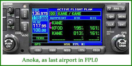
Both of these methods however require multiple button pushes to achieve the desired result. And if you are in an emergency situation, the less button pushing you have to do, the better your chances are of achieving a successful outcome. There is a neat little trick that will achieve this. When you program FPL0, simply add your departure airport a second time, as the last airport in FPL0. Now FPL0 looks like this.


The software in the Garmin 430 has it bring up approaches for the last airport in FPL0 when PROC is selected. And since your departure airport is the last airport in FPL0, PROC brings up the approaches for Anoka.


Once you are on your way and things are proceeding without incident, you can simply delete that last entry for Anoka in FPL0. To do this, go to FPL0, turn on the cursor, and move it to that last KANE entry by using the large (outer) knob. Warning - if you try to reposition the cursor with the small knob, the Garmin thinks you wish to enter a new waypoint and brings up the appropriate dialog box. Once you have the second KANE highlighted, simply press CLR. You will be asked to confirm that you want to delete the waypoint. Answer YES, and the second KANE disappears


Caveat - if you have recentered your CDI by pressing DIRECT-TO, this procedure will not work. The DIRECT-TO takes priority over FPL0. In this case, you either have to cancel the DIRECT-TO by pressing DIRECT-TO, MENU and select CANCEL-DIRECT-TO or going into FPL0, turning on the cursor, highlighting KANE and doing a DIRECT-TO.


Putting the departure airport as the last waypoint in FPL0 is strictly for an emergency. But if you are in the clouds, your left engine is on fire, you are icing, and your right-seat passenger is throwing up on you, it will serve as a very effective means of getting you back into Dodge in a hurry and with the least amount of button pushing.

In the interest of disclosure, I should also add that this stratagem is not mine. I saw it outlined recently in AVweb, a popular aviation website . I thought it was pretty neat trick, and investigated exactly how it would work and what its shortcomings might be.

Friday, February 19, 2010

Reverse Sensing? No Such Thing

I often hear comments from pilots about confusion over normal sensing and reverse sensing. To some it seems no big deal, but to others it is a source of worry and confusion. I am going to make what may seem to be a rather startling comment to some of you.


If you truly understand VOR navigation, there is no such thing as reverse sensing.


Okay, bear with me. The confusion arises because the majority of pilots have been taught to “fly towards the needle” when learning VOR navigation. That in turn gets interpreted to mean fly either right or left in order to get on the desired course. And therein lies the problem and the source of the confusion.


You do not fly towards the needle. Instead you fly towards a heading, and that may mean fly either right or left. It depends on where the nose of the aircraft is pointing.


In the above figure, the OBS is set to 360, same direction as the nose of the aircraft. So students have been taught to fly towards the needle, or to the left. But instead of right or left, think heading. Looking at the VOR display, a heading of 270° will take you directly to the selected course. In this case that does happen to be a turn towards the left. But now let’s spin the aircraft around, so it is flying south.


Notice the VOR display has not changed. The VOR head (as the VOR display is technically called) neither knows nor cares where the nose of the aircraft is pointed. The CDI is still deflected to the left. It is still saying that to get directly to the selected course, you need to fly a heading of 270 degrees. But now look at the DG (or heading indicator). A heading of 270° is towards your right – in the opposite direction of the needle. This, then, is the so-called reverse sensing. But if you think heading rather than right or left, there is no reverse sensing. Instead there is just a heading to fly, and that heading may be to your left or to your right.


This works for localizer as well as VOR courses. Let’s take a look at the ILS-18 into Lebanon, NH (KLEB). Here is what the instruments look like as the pilot is being vectored for the ILS, flying a heading of north. Look at the approach plate first and see where the aircraft is.


Now let’s look at the aircraft instruments. Note the aircraft is flying north, on the east side of the localizer. The VOR display says the pilot needs to fly towards the west to get to the localizer course. The DG (heading indicator) says this means a turn towards the left. Think heading, not right or left!


Now let’s look at tracking inbound on the localizer. Again, first look at the approach plate to see where the aircraft is.


Now let’s look at the instruments. Note that the aircraft is slightly west of the localizer course. The instruments show exactly the same thing – the aircraft is slightly west of course. Also note in both cases, the OBS for the VOR display is set to the final approach course. If you set the OBS to the final approach course, it results in less knob twisting, and in a busy cockpit, this is an advantage.


So you see that if you disavow yourself of the “fly right or left or towards or away from the needle” way of thinking, the entire concept of reverse sensing simply disappears.

I’ve shown it here for a localizer, since this notion of reverse sensing is very common when either flying a back course or tracking outbound on a localizer to do a procedure turn. But it works exactly the same way for tracking on a VOR approach.


Let’s look at the VOR-25/LEB. Below is a portion of the approach plate, showing the position of the aircraft being vectored for the approach.


Now let’s look at the instruments. The aircraft is being vectored on the east side of the final approach course. The OBS is set to the final approach course. The needle is deflected to the right and a heading of 330° would take us directly to the final approach course. But 330°is to our left, away from the needle. Think heading, not right or left.


Now let’s look at the picture as the aircraft has been given a heading that provides an intercept for the final approach course. First look at the approach and see where the aircraft is.


The aircraft is on a heading of 280°, just about ready to join the final approach course. This is what the instruments look like.


If you think heading rather than right or left, you can set the OBS to the final approach course, even if you are flying outbound to do a procedure turn. By the way, with an HSI you always set the course to the final approach course, sometimes called the front course, even if you are flying a Localizer-Back-Course approach.

If you are used to always setting the OBS to your heading, as students have been traditionally taught, then continue with the procedure if you are comfortable with it. However you decide to do it, though, think heading – not right or left.


I close this discussion with the following acronym.


IBOT


I have used it for a long time to help students remember what radial they are on.


I = inbound or “TO” flag on VOR head

B = radial is at the bottom of the VOR head

O = outbound or “FROM” flag on the VOR head

T = radial is at the top of the VOR head


So think “inbound bottom” and “outbound top.”


Try out some of the ideas I’ve presented here yourself. You will find out they work, and they can significantly reduce the amount of confusion that occurs when doing VOR navigation.


Sunday, February 07, 2010

True, False or Maybe

Instrument flying is chock full of rules and regulations. However it is also replete with gray areas, where a clear definitive answer is not spelled out. These areas are always good to spark a lively debate among pilots. Instructors are no different – we have our ideas too about the gray areas. So let’s look at a few things that are not clearly spelled out and are sure to provoke some debate.


Question 1:

Scenario: you are flying towards the IAF for the NDB or GPS RWY 34 at Cambridge (KCBG). You have been cleared for the full approach, your direction of flight is northwest and your altitude is 4000’ MSL.


After passing over the IAF, you must get established on the outbound leg with a heading of 170° in order to do a procedure turn. Which is the true statement?

· You must make a right-hand turn to get established on the outbound course because that is the protected side shown for the hold.

· It doesn’t make any difference whether you turn right or left because you are at MVA and not in any danger of colliding with an obstacle.

Question 2:

For the same approach, for various reasons you are at an altitude of 8,000’ and need to lose a lot of altitude in order to fly this approach. ATC tells you to hold south of the NDB IAF as published and descend in the hold until you reach 3,000’.


You do as directed and reach 3000’ as you are approaching the IAF on the inbound leg of the hold. ATC clears you for the full approach.


True or false:

· You must intercept the outbound leg in order to fly out and do a procedure turn.

· You can simply extend the outbound leg of the hold for two minutes or so and then turn inbound in the elongated holding pattern.

· Both procedures are acceptable.


Bonus question:

· What is DUMDY? (Hint – it is not shorthand for Descend Undercarriage Mixture Descend some more and Yippee there’s a runway in sight)


Question 3:

Now let’s look at another approach, this one is the GPS-28 approach into Maple Lake (KMGG). Scenario: you are approaching NAZMY from the east. ATC has cleared you for the approach.


You are pretty much lined up with the final approach course but the approach plate doesn’t specify NoPT coming from this direction and the 1-minute hold depicted at NAZMY is clearly meant to serve as a procedure turn.


True or false:

· You must do a turn around holding because NoPT is not specified

· You don’t have to do a turn around holding because you are more or less lined up with the final approach course


Question 4:

You are flying the full VOR-A approach into KMIC (see IAP below). You have completed your outbound leg on the procedure turn and are ready to do a 180° turn to a heading of 121° to intercept the inbound course.


You happen to glance at your DME and it reads 9 nm. The profile view clearly states the procedure turn must be done inside of 10 nm. Which of these statements is true?

· You must turn right because that is how the procedure turn is depicted on the approach plate.

· It makes no difference which way you turn, so make a left-hand turn to 121° in order to stay within the 10 nm range for the procedure turn.


Second bonus question:

You are flying single-pilot IFR and are trying to get the weather at your destination. But just about the time the ATIS report is giving the winds, ATC starts talking again so you turn down the volume on the ATIS frequency in order to hear the controller. After several attempts to get the weather, you still don’t have the pertinent information and are getting closer and closer to your destination.

What is your best course of action?


· You never leave the ATC frequency, so just hang in there and keep trying. Maybe you’ll get lucky.

· Ask ATC for permission to leave the frequency to get the weather at your destination


Answers:


As I said at the start, these are areas that can provoke a lot of discussion among pilots, so here is my two cents worth.


Question 1:

It makes no difference which way you turn in order to get established outbound.


Question 2:

Both procedures are acceptable.


First bonus question:

DUMDY is a procedural waypoint for an IFR GPS. An IFR GPS starts scaling down to 0.3 nm sensitivity two miles before reaching the FAF. However this approach does not have a FAF; you simply start to descend when established inbound. DUMDY serves as a virtual FAF for an IFR GPS. Two miles before reaching DUMDY the GPS starts scaling down to 0.3 nm sensitivity. And as a sidebar, if flying this as a GPS approach, you had better not start your procedure turn until you are south of DUMDY.


Question 3:

The second answer is correct. ATC is not expecting you to do a procedure turn. In the AIM, this is clarified, and controllers will often clear you straight in for the approach. If there is any doubt in your mind, however, query the controller about it.


Question 4:

The second one is preferred. It makes no difference which way you turn, and a left-hand turn will more likely keep you within the 10 nm limit.


Second bonus question:

The second course of action is preferable. You won’t read this in any book, but I have had both controllers and DPEs tell me they would prefer pilots ask for a frequency change to get the weather. Otherwise you are trying to listen to two frequencies at once and risk missing a call or not getting the weather (or both).


In the future I’ll try to delve into some of issues and questions like this. Your suggestions for future topics are welcome.


Wednesday, January 27, 2010

Silence

I have not been posting for a long time. Busy is about my only excuse. But I've had many requests to start posting again. So I will start again in the near future.

It is very nice to know that many people read the blog and that it has proven helpful in some ways.

Linda

Tuesday, May 27, 2008

Audio Panels Demystified

As instructors we are sometimes quite guilty of assuming “everyone knows that”, whatever “that” may be. Just a simple question from a student however can quickly make us realize it’s a false assumption. So it was a question from a student concerning the operation of an audio panel made me realize that it is probably worth offering some explanation about its operation.


The audio panel in question was the KMA 24, probably one of the most common audio panels found in planes.


In an overall view, the KMA 24 audio panel has two rows of buttons, flanked on the left by marker beacon lights and on the right by a rotary knob whose principle function allows the user to select COM 1 or COM 2. The top row of buttons directs the selected audio output to the speaker in the aircraft. The bottom row of buttons directs the selected audio output to your headset.


  1. Marker beacon lights are used in many ILS instrument approaches. If the ILS approach has marker beacons (not all of them do), the most common ones are the outer marker (the blue light marked “O”) and the middle marker (the amber light marked “M”). The inner/airway marker (the white light marked “A”) is generally only installed at major airports. Marker beacons emit a 75-Mhz signal. When the aircraft passes over an outer marker, the blue marker beacon light is seen. A middle marker beacon illuminates the amber marker beacon light. In addition, an audible tone may be heard. If you want the audible signal to come through the speaker, press MKR (#9) on the top row of buttons. If you want it to come through your headset, press MKR on the bottom row of buttons.
    1. The 75 Mhz signal transmitted by the marker beacons is a carrier frequency. This carrier frequency is modulated into a 400 hz, 1300 hz or 3000 hz signal for the OM, the MM, and the IM respectively.
  2. TST - test the marker beacon lights. Pressing this button causes all the marker beacon lamps to illuminate. SENS - the button just to the right of the amber marker beacon lamp selects the sensitivity of the marker beacons. HI allows the marker beacon signal to be detected approximately one mile before passing over the beacon. At this point, if you had HI sensitivity selected, you would want to switch to LO sensitivity. A word of caution concerning the TST button. Bendix King notes that the TST button should not be pushed when the autopilot is coupled on an ILS approach. Some autopilots, including Bendix King models, use the marker beacons to change the sensitivity of the autopilot. Next to the “O” marker beacon lamp is a photoelectric cell which controls the brightness of the marker beacon lamps.
  3. TEL – controls audio for a radio telephone. Alternately some KMA 24 audio panels replace the TEL function with HF, for operation with a high frequency transceiver. Note that this function, either TEL or HF, must also be selected on the rotary knob on the right side of the audio panel.
  4. 1 COM – controls audio received from COM 1 communications radio. Again, the top row button directs output to the aircraft speaker, and the bottom row button directs it to your headset.
  5. COM 2 – controls audio received from COM 2 communications radio.
  6. 1 NAV – controls the audio received from the NAV 1 radio. This includes any weather information, such as HIWAS as well as the Morse code IDENT. Many nav radios have a switch on the radio for IDENT. This must be selected in addition to selecting either speaker or headset for the audio.
  7. NAV 2 – ditto for the NAV 2 radio.
  8. DME – allows you to hear the Morse code identifier for any DME that is co-located with VOR or localizer stations. Most DME receivers have the ability to enter a frequency separately from the nav radios. However the most common method of operation is to remote the DME receiver to either nav 1 or nav 2.
  9. MKR – allows you to hear the marker beacon audio signals.
  10. ADF – allows you to hear the Morse code identifier of an NDB station. During an NDB approach, most instructors teach their students to keep the Morse code identifier for the NDB on during the entire approach to verify integrity of the signal. Unlike VOR receivers, ADF receivers do not display an OFF flag, so the Morse code is the only way to ensure the data being received by the ADF receiver is valid.
  11. AUTO – this is probably the most confusing button for pilots when they first work with the audio panel. The rotary switch on the right side of the KMA 24 can be set for either COM 1 or COM 2. The rotary switch controls the transmission frequency. So if you have COM 1 selected with the rotary switch, when you push the transmit button, you are transmitting on COM 1. The AUTO button allows you to automatically slave the received audio information to whichever frequency you have selected with the rotary switch. By pressing the AUTO button in the bottom row (headset), you will automatically hear the transmissions from either COM 1 or COM 2, depending on which one has been selected by the rotary switch. So with AUTO selected, you may switch back and forth between COM 1 and COM 2 with the rotary switch without having to reselect COM 1 or COM 2 using the push buttons. If you desire to hear audio from the other com radio, you may do so by simply pressing the appropriate button for either speaker or headset. For example you are listening and transmitting on COM 1 but would like to listen to ATIS at the same time. You may do this by putting the ATIS frequency in COM 2 and pressing the COM 2 button for either speaker or headset. Warning – it can be confusing to try to listen to two frequencies at the same time.
  12. The rotary switch on the right side is used to select the desired transmitter for the cockpit microphones. COM 1 and COM 2 have been previously discussed. The INT position selects cabin intercom. This allows the crew to address the passengers over the cabin speaker. The EXT position allows the crew to address people on the ramp through an external ramp hailer speaker, if one is installed.


In putting this discussion together, I found a good pilot guide to operation of the KMA 24 audio panel on the Bendix King website. It is a downloadable pdf file, and the web address is


Pilot Guide to the KMA 24 Audio Panel